Vinyl Record Player
Before my 2025 Christmas, I received a vinyl record album from my Intro to Electrical Engineering TA, Yihao, during a game of white elephant. I thought I could learn a lot if I tried to make the record player myself. Also, the satisfaction of being able to play the record for the first time would be incredible.
If you're curious, this is the album I received:

Anyways, I had to separate this project into many small parts. I’m not sure how much of this will be designed by scratch. I’ll probably decide as I go along the journey.
1. the turntable (the record spinner)
a. electrical hardware (the pcb)
b. mechanical hardware (base, motor mounts, pulley)
c. firmware (hall effect sensor rpm measurement, pid speed tuning)
2. the tonearm (what reads the vinyl)
a. the tonearm (pivoting arm)
b. the cartridge (pin on end of arm, contacting vinyl)
3. the audio chain
a. phono preamp (amplifies tiny signal from cartridge)
b. amplifier (amplifies signal to drive speakers)
c. speakers (convert signal to sound)
THE TURNTABLE:
MOTOR CONTROL PCB:
The first thing I needed to do was understand what my electrical system needed to complete. I needed to size a motor that could support the turntable, was easy to power, and minimized vibrations/disturbances in the audio signal.
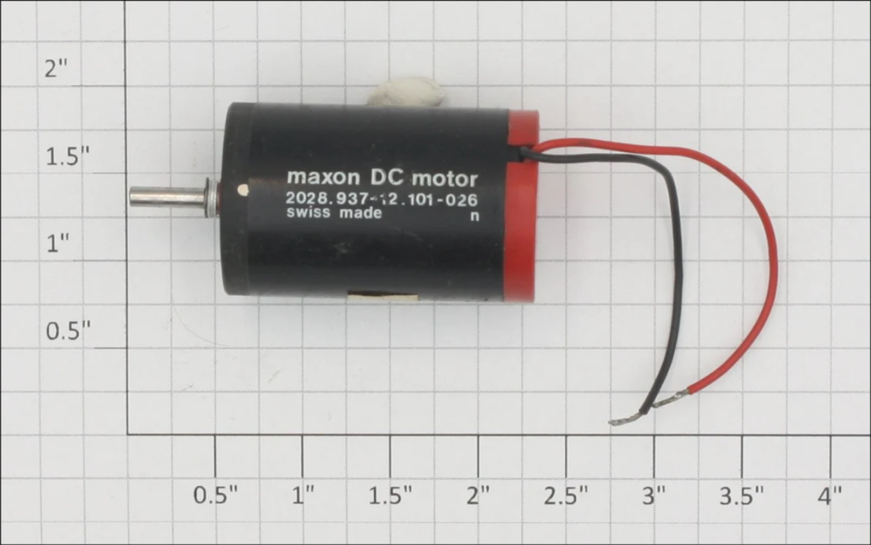
In common DC motors, the iron core creates magnetic “detents” which cause small speed variations as the motor spins. These little bumps of resistance are even more noticeable at low RPMs, which our turntable will be running on. Compared to normal DC motors, coreless DC motors reduce these variations by lacking a conventional iron core. Additionally coreless DC motors are generally known for their stability. After a bit of research, I purchased the maxon 2028.937-12.101-026 Coreless Brushed 12V DC motor.
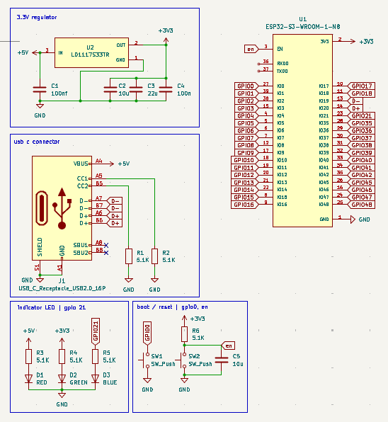
Since I’ve decided on a motor, I could begin the circuit design. I based the board on an ESP-32-S3 chip and got to work. I set up the basic circuit for an ESP-32-S3 breakout board. I connected two 5.1K resistors to the USB C connector to signal a sink device and receive +5V from the power supply and used an LDO to bring that down to +3.3V for the MCU.
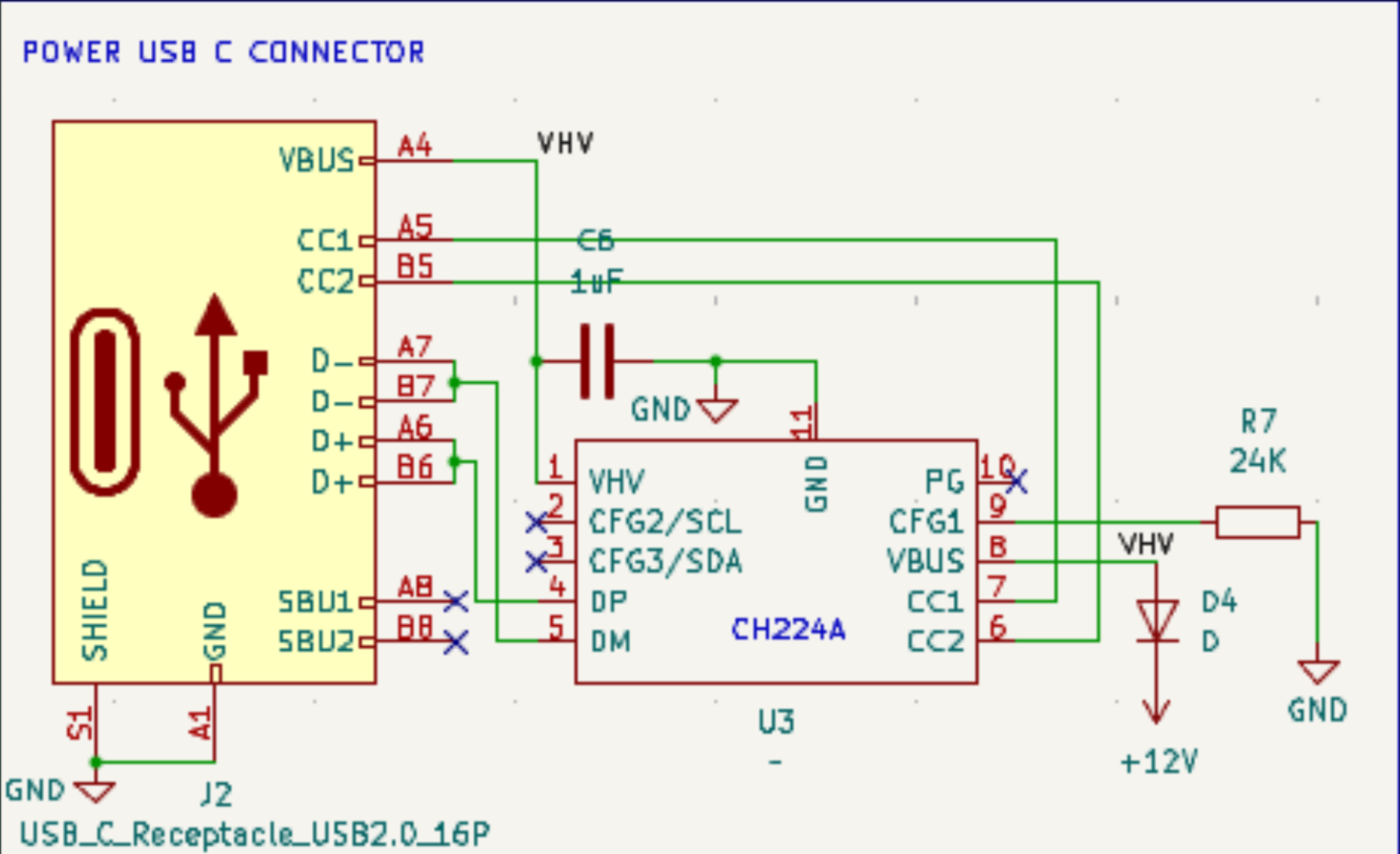
To power my motor, I had to update this design to receive +12V instead. I found a chip, the CH224A that I could use to handle the USB PD behavior. All I had to do was attach a 24K resistor connecting pin CFG1 to GND.
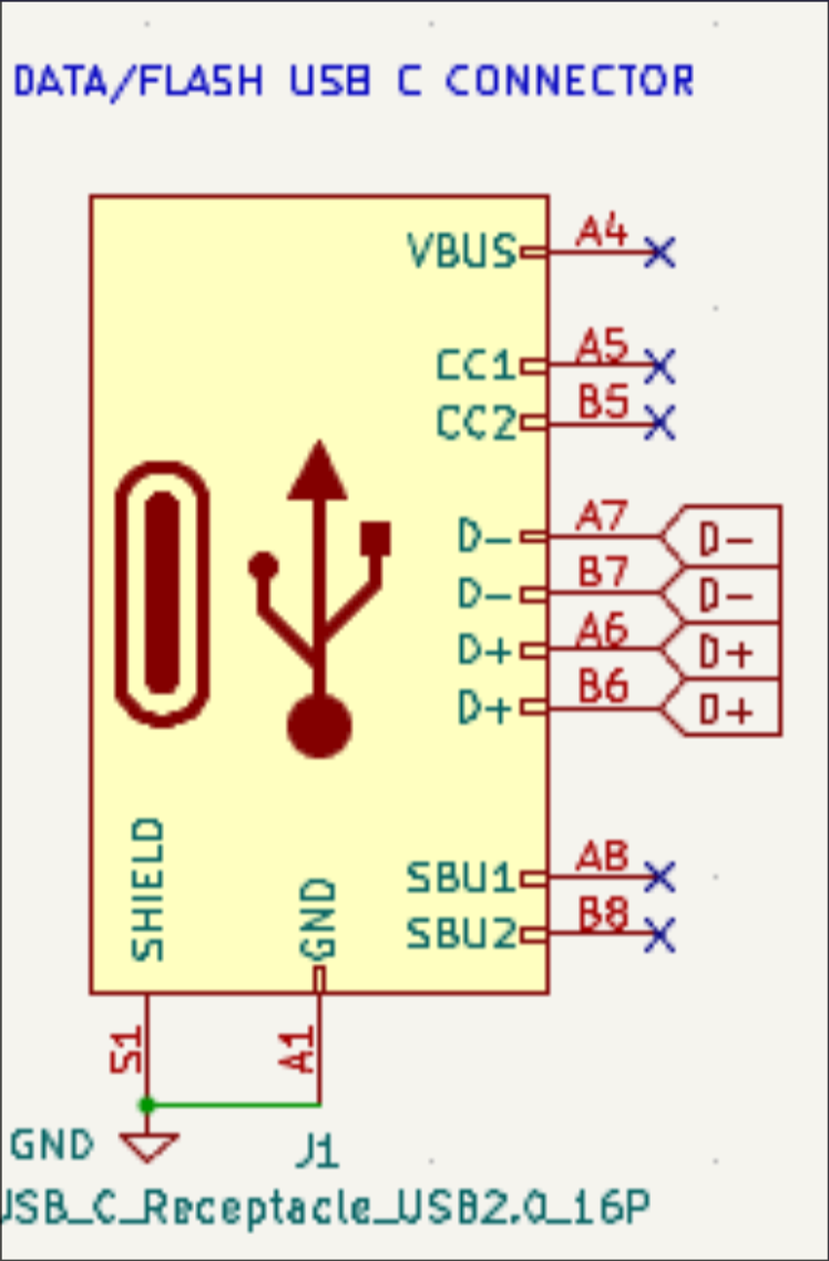
Since the data pins on that USB C connector were occupied, I added another one just for flashing the MCU. In the future, I should probably use JTAG or UART to flash. I think you can even use WIFI or Bluetooth to flash ESP32 chips.
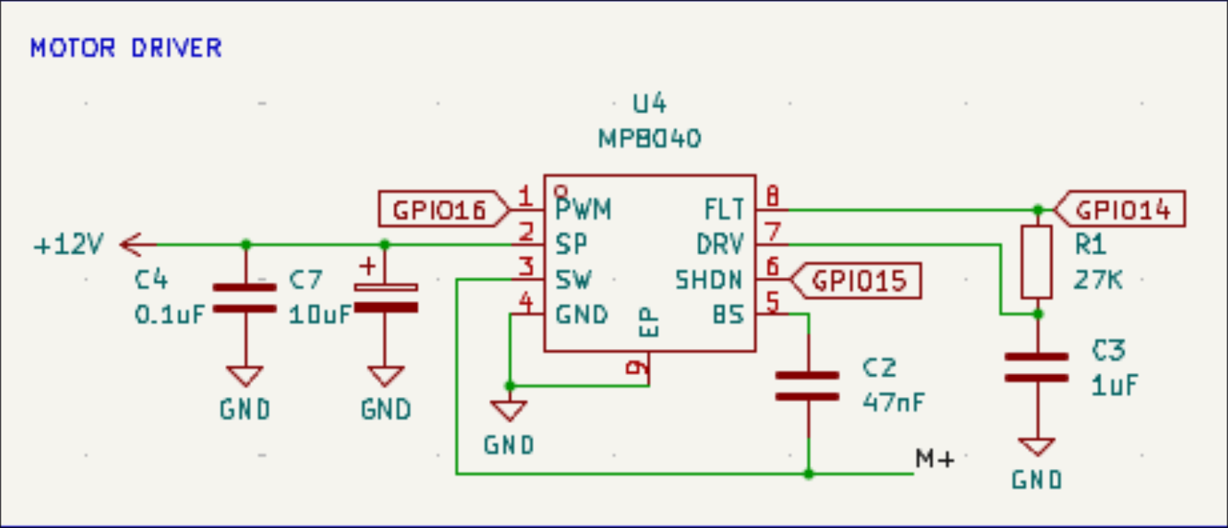
Once I was able to receive +12V, I needed to control it precisely with PWM. I measured the stall current of my motor at ~6A and found the MP8040 half bridge power driver to be suitable for my needs. I wired it according to the typical application listed in the datasheet, added some breakout pins, and got ready to route my circuit board.
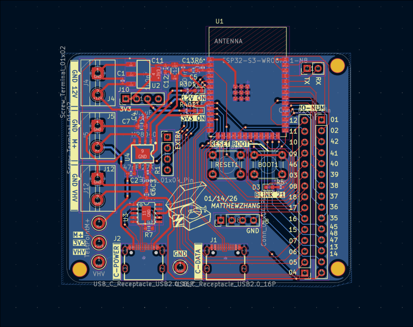
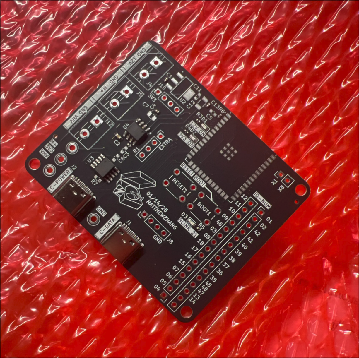
Routing the PCB was so satisfying, I could definitely do that again. I drew up a small logo to put on the silkscreen and sent it off to JLCPCB.
Receiving the board I designed in the mail was really exciting. However, I realized a potential mistake I made in my board. During my interview for Texas Aerial Robotics (one of the organizations on campus) I was given a question about powering DC motors. During this interview, I realized I forgot to add a flyback diode to my circuit.
EDIT-IN-POST: The flyback diode is not actually necessary here because the MP8040 integrates two MOSFETs in a half-bridge which already provides body diodes for the current in the motor to recirculate. Still, something I didn’t catch (and I’m learning) so I think it’s worth explaining.
Why might a flyback diode be required?
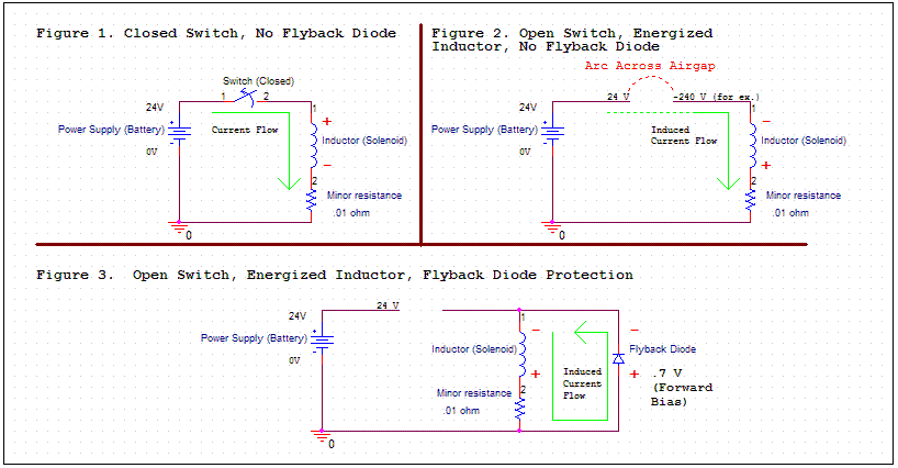
A motor can be modeled as an inductor and a resistor in series. If current is flowing through that inductor at a steady state and I suddenly cut it off, the inductor will try to keep current flowing. However, there's nowhere for current to flow to, so the inductor tries to force current to continue flowing by accumulating a massive voltage difference across its terminals.
Anyways, this large spike in voltage can damage sensitive electronics on the same Vbus. The inductor will generate whatever voltage it can to keep current flowing. At times, it can even pull electrons out of the air to create arcs.
A flyback diode can prevent all of this by providing the inductor a safe path to route current. It sends the current back through the motor’s resistance and dissipates the stored energy as heat.
Well, I got the board soldered and found a spare diode. I sized the diode by finding one rated above my motor's stall current and supply voltage. SMD soldering with solder paste and a heat gun is so fun, it just goes right where it should.
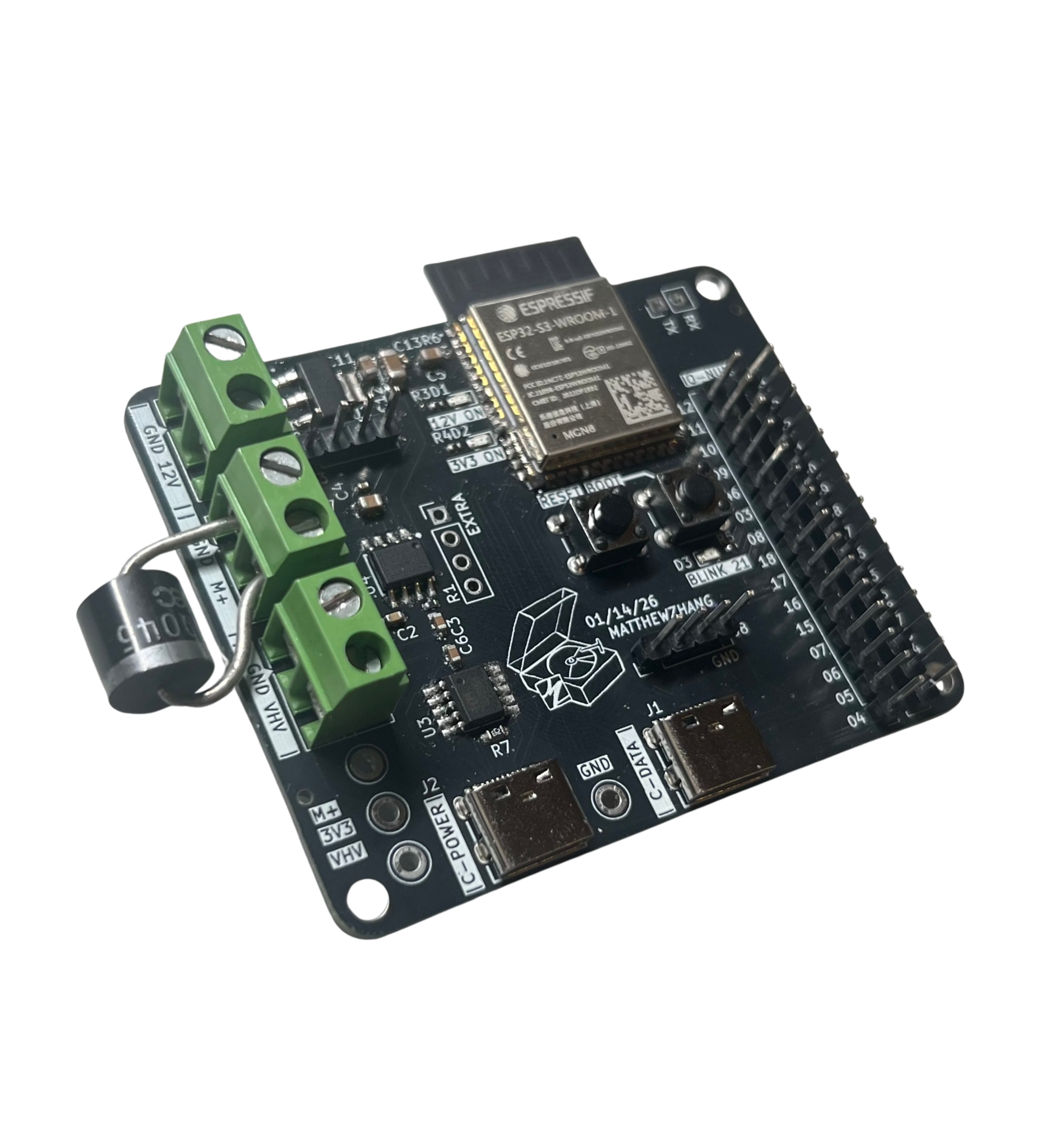
After I confirmed the MCU itself worked, I added the MP4080 pins to my test program, connected my motor, and ran it for the first time!

The PCB works. Now it's time to move onto the firmware. I'll do a little more CAD to get a basic turntable setup working and then I'll connect the hall effect sensor to create a small PID control program.
MECHANICAL DESIGN:
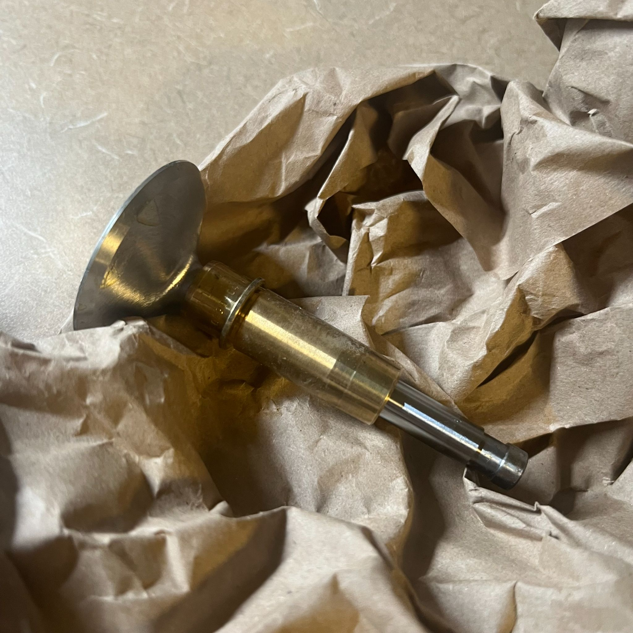
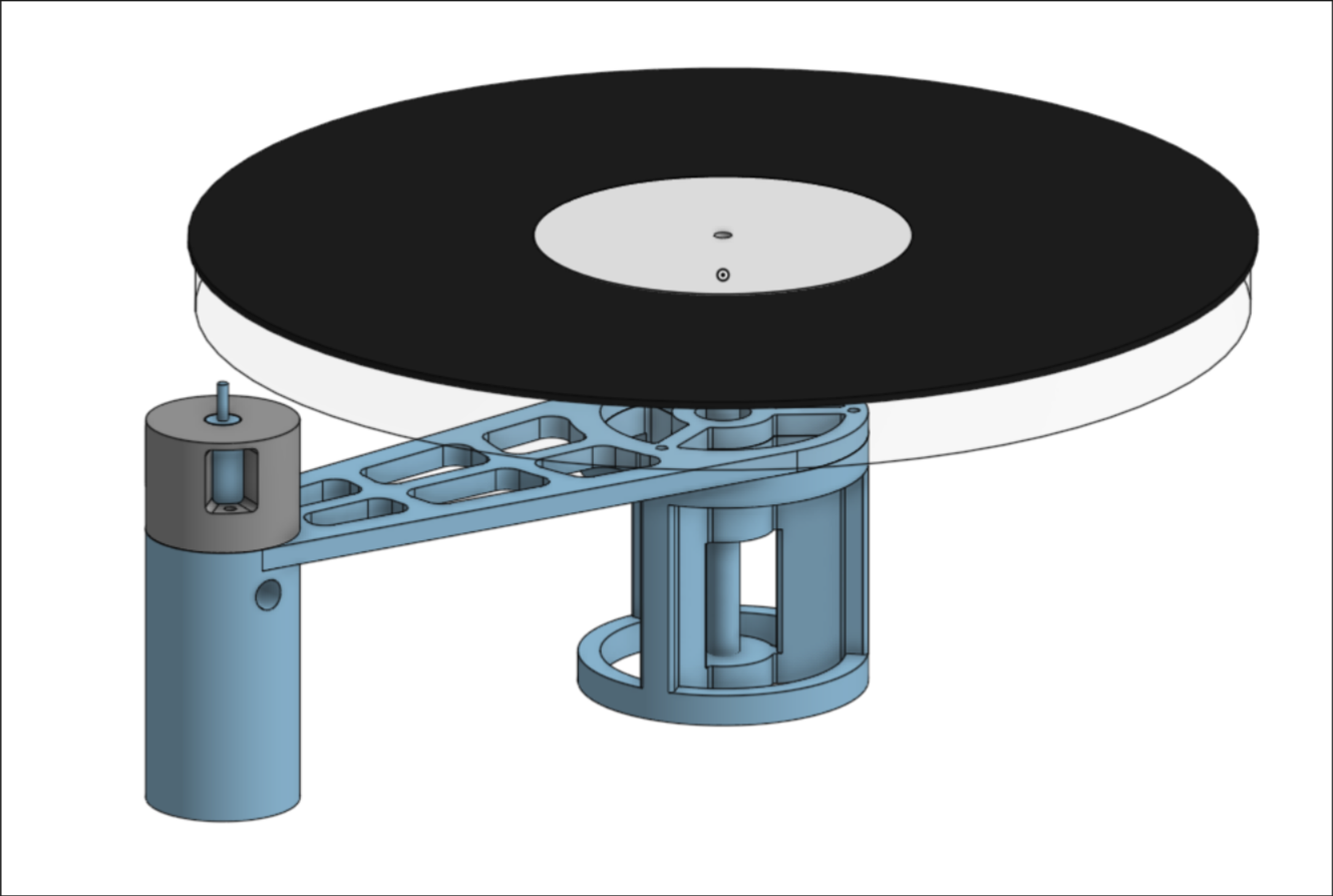
This project takes a lot of inspiration from the ALTMANN turntable. Before this project, I've never taken the time to research what goes into making good sound on a record player. The turntable must spin smoothly with minimal disturbances and noise. I followed Altmann's setup and found a similar motorcycle intake-valve and valve guide setup to use for the turntable's main bearing.
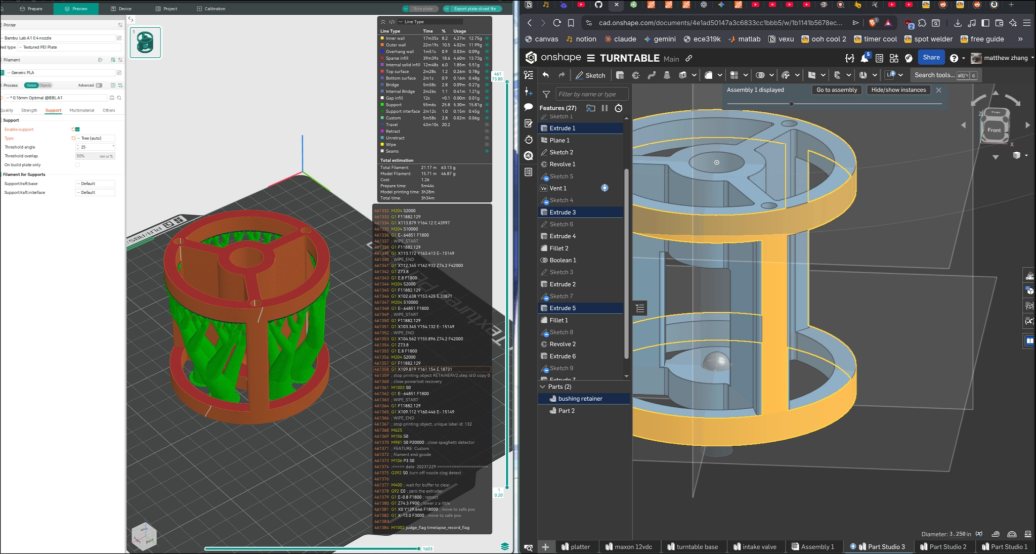
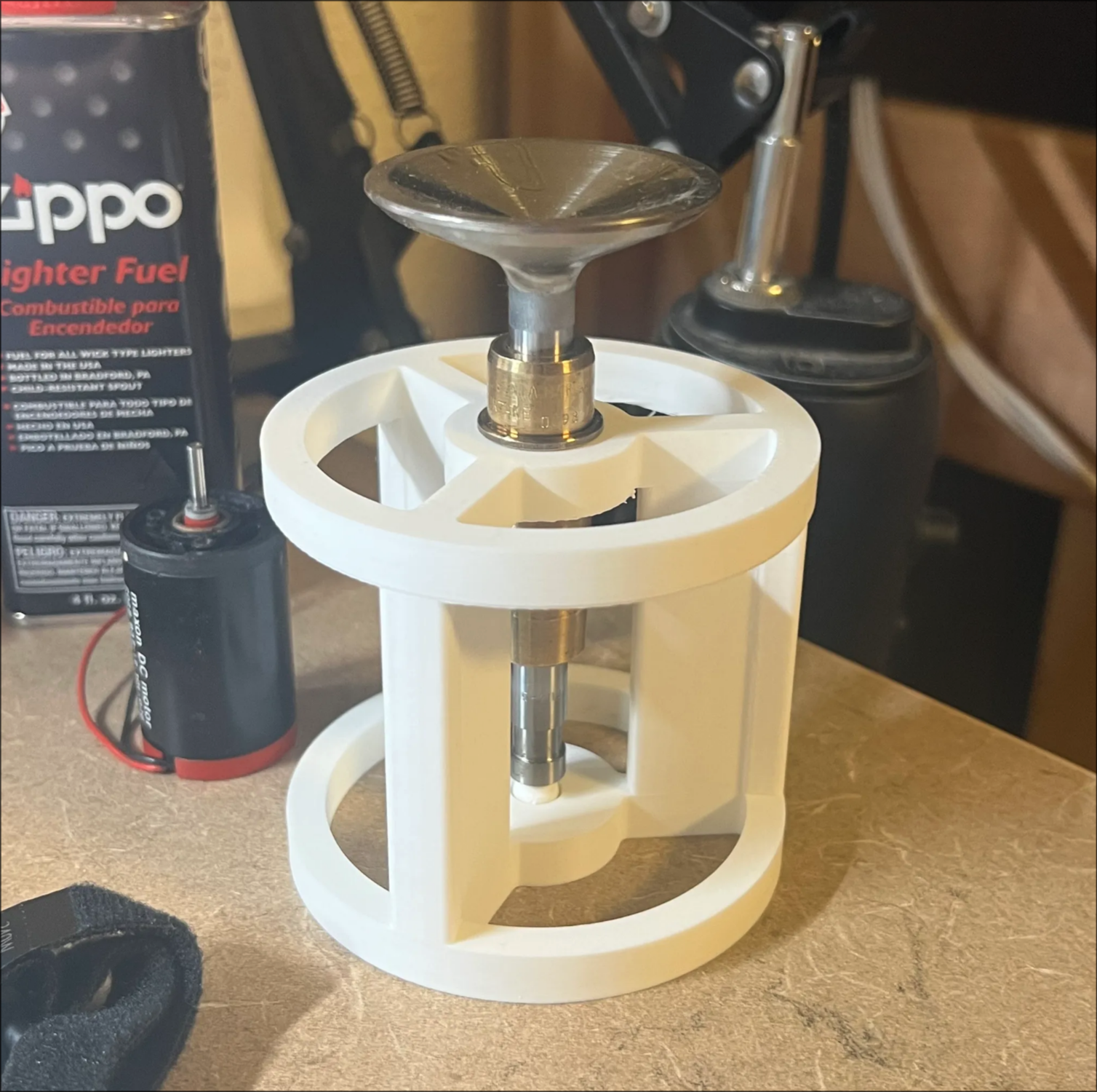
there it is, a quick CAD for a temporary base, and in person!
I didn't have the tools nor wood to create my own custom wooden platter so I found an acrylic platter replacement for a different brand online for this project. I'm not certain how I'll mount the platter yet. I'll have to try a few different methods in CAD.
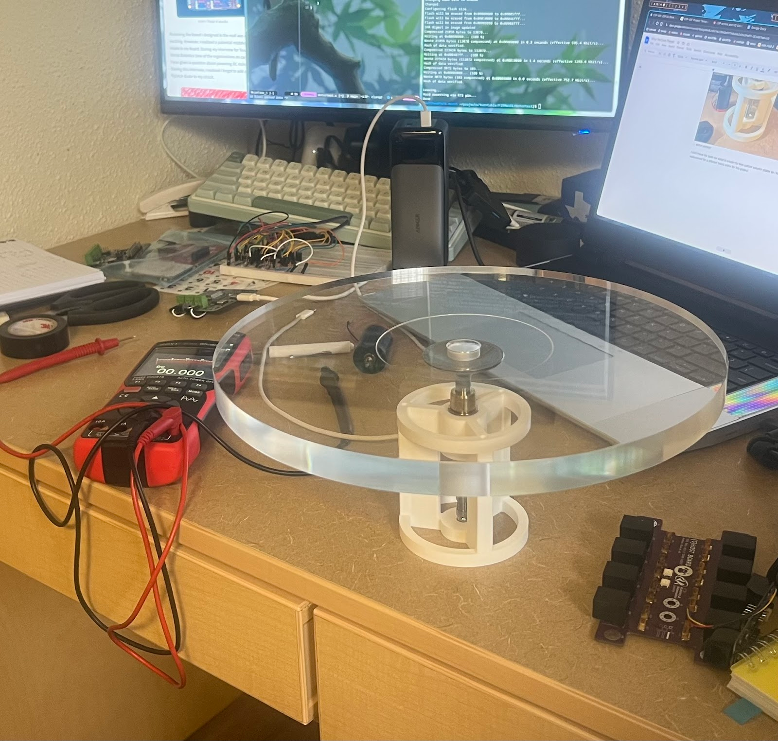
I created a test CAD rig just so I could mount the motor and start testing my PID loop with the platter RPM while I wait for materials for a real turntable base.
MOTOR CONTROL PCB V2:
So I was testing the US5881 Hall Effect Sensor and I got it working well. I started doing some tests with the assembled setup, toggling the onboard LED and seeing if I could calculate a fake RPM from me waving the magnet back and forth. Then suddenly, the +3.3V rail’s LED turned off, as well as my program. I felt around the PCB. The LDO was burning hot.
Seems like I’ll need to redo part of the circuit. I was due for this anyway because I’d like to add more components to it rather than having wires strewn about. And since I know the USB-C PD is faultless, I can remove some redundancies in the board.
I’ve outlined my mistake in the image provided.
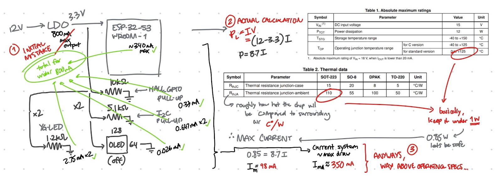
Essentially, I read the datasheet too quickly and used the first number I saw for a “maximum current” instead of actually calculating the power loss and fully understanding the operation of the LDO. If I had read through the datasheet properly, I’d likely have realized that an LDO is unfit for this task.