IEEE Robotathon Team #9
My friend, Kevin, invited me to join him to compete in the 2025 IEEE Robotics & Automation Society Robotathon. It’s an annual competition hosted by upperclassmen at UT Austin for ten teams of ten underclassmen to get an introduction to robotics.
The competition spans several weeks, however we are only given a brief description of our tasks until a day before the tournament. This is meant to prevent hard coding challenges that are meant to be performed autonomously, but it also makes mechanical design difficult because we aren’t given dimensions, sizing, or even clear objectives.
What we were told was that we would be completing these tasks:
1.) navigating a maze autonomously
2.) navigating towards colors on the field
3.) following a line
4.) and launching ping pong balls into a tiered structure.
THE LAUNCHER:
In this project, I was responsible for the mechanical design of the robot. The moment I heard the words ‘launch’ and ‘ball’ I immediately gravitated towards my past experiences in FRC. Ball launchers are very common in FRC. They’re designed with massive, heavy flywheels and are often hooded to improve accuracy. But I figured for this competition, that level of precision wouldn’t be necessary.
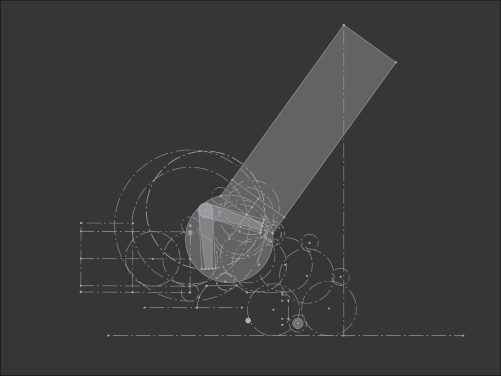
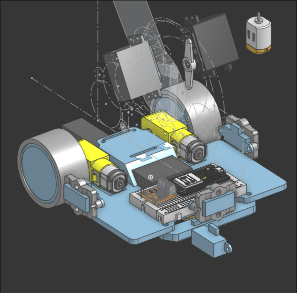
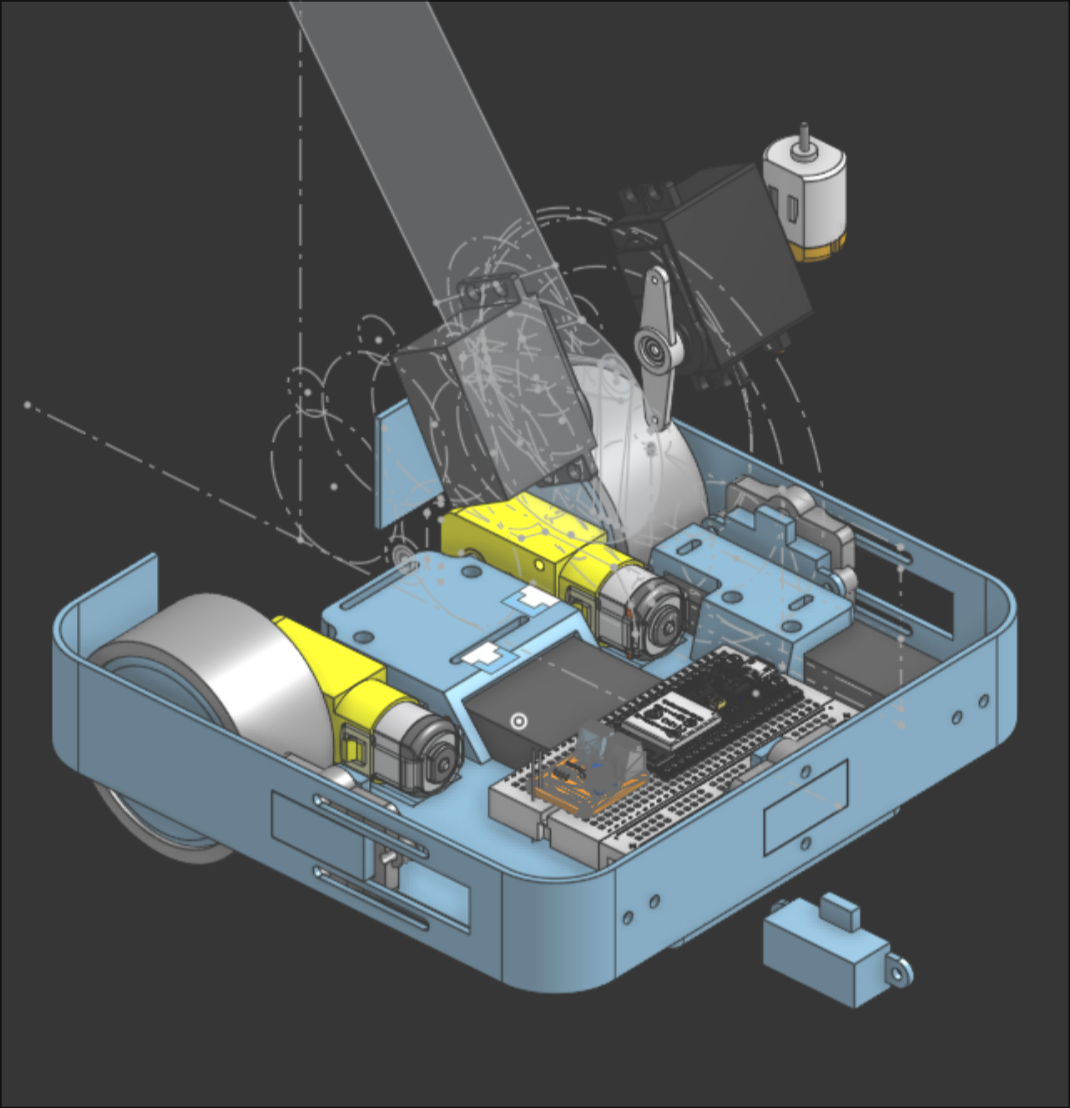
These were initial sketches and designs for the robot’s shooter.
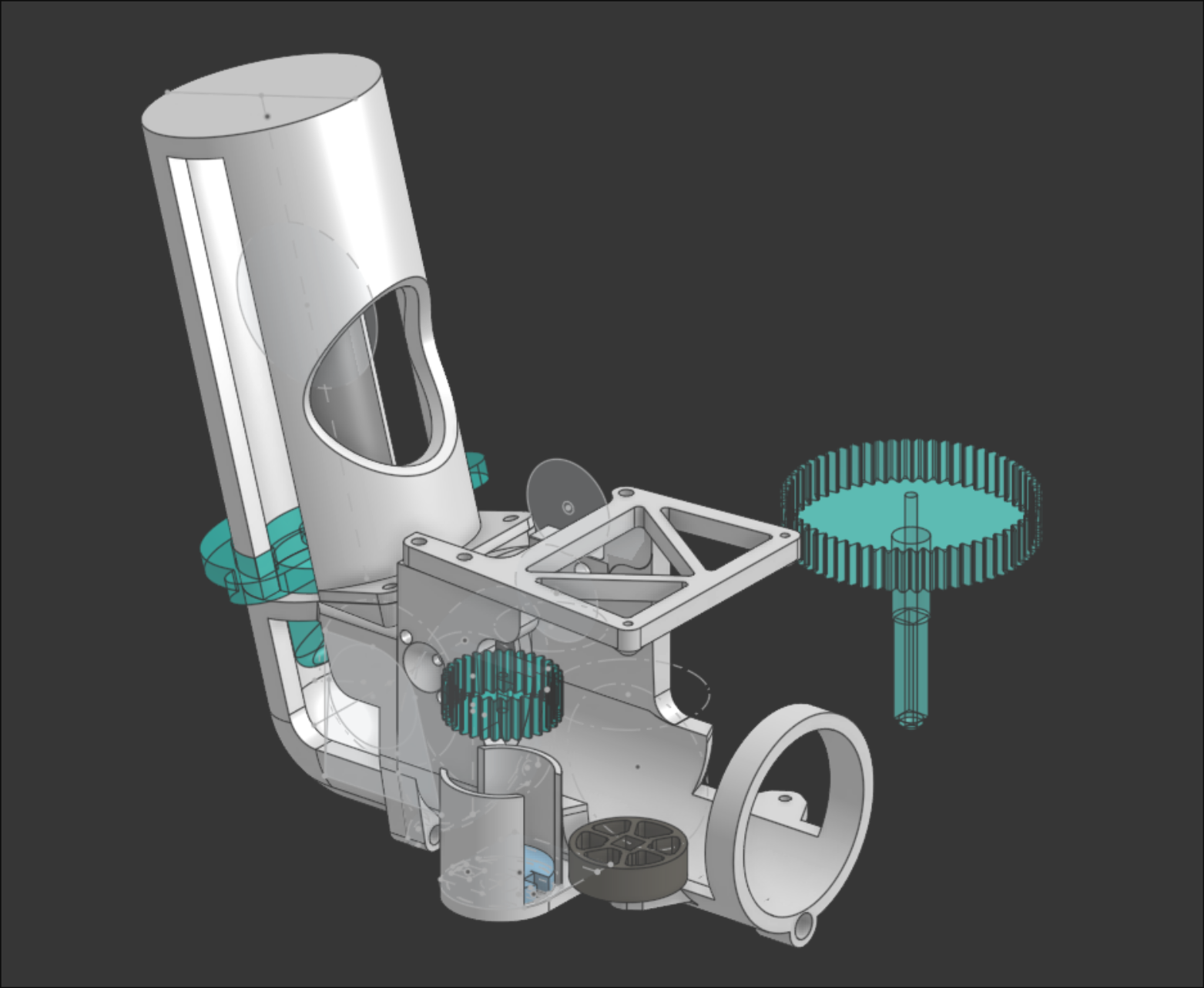
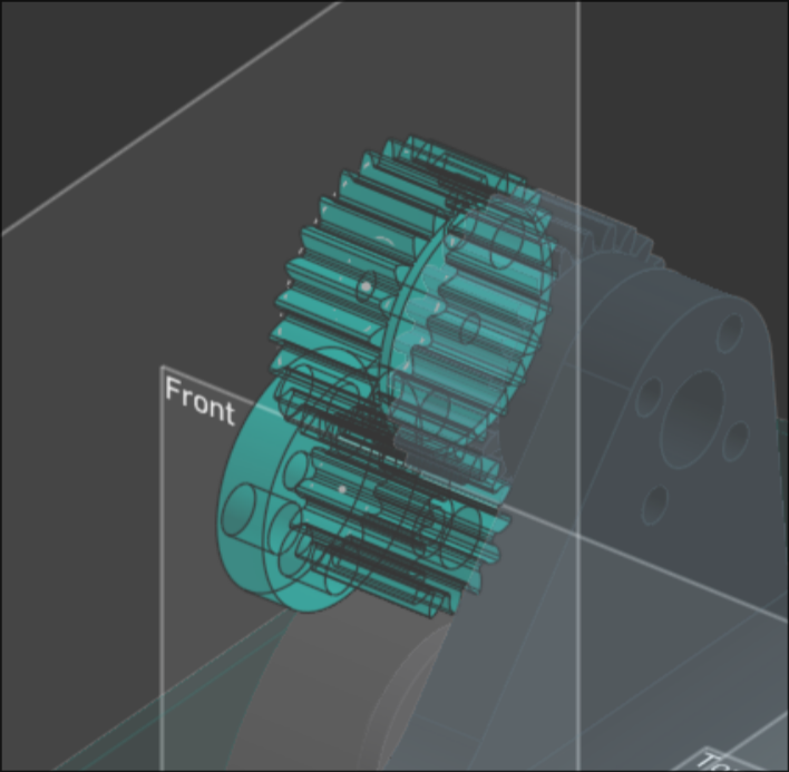
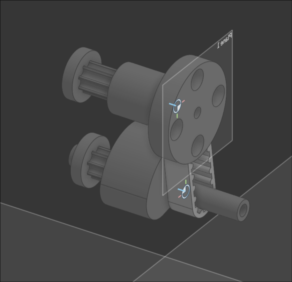
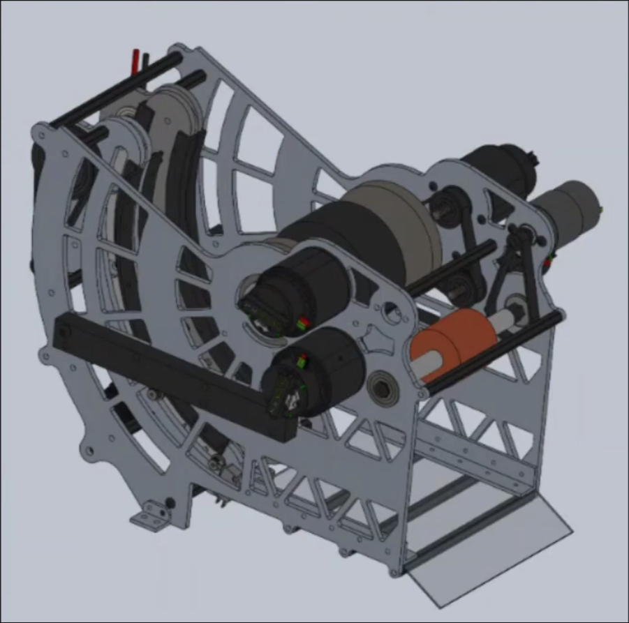
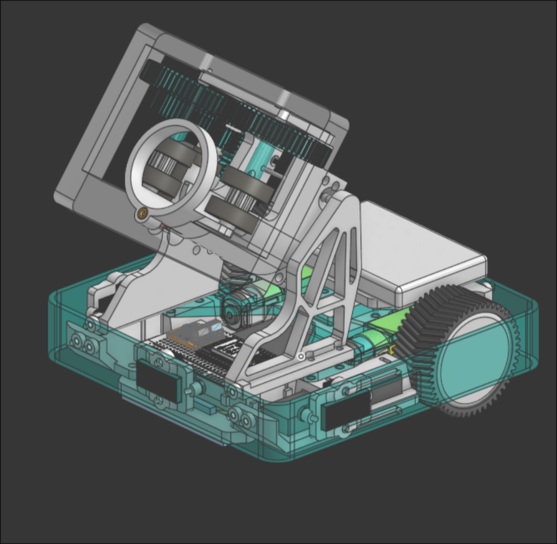
cad and cad (i used onshape for how easy it is to work together & share files)
The tube sitting behind the shooter is meant to be a spring-loaded magazine. I thought we were required to hold onto the balls we were tasked to shoot. Later I found that it wasn't necessary so I removed the magazine. My first few attempts at making the gears were very susceptible to slipping. I had to try a few times before I had the right tolerances and they meshed properly.
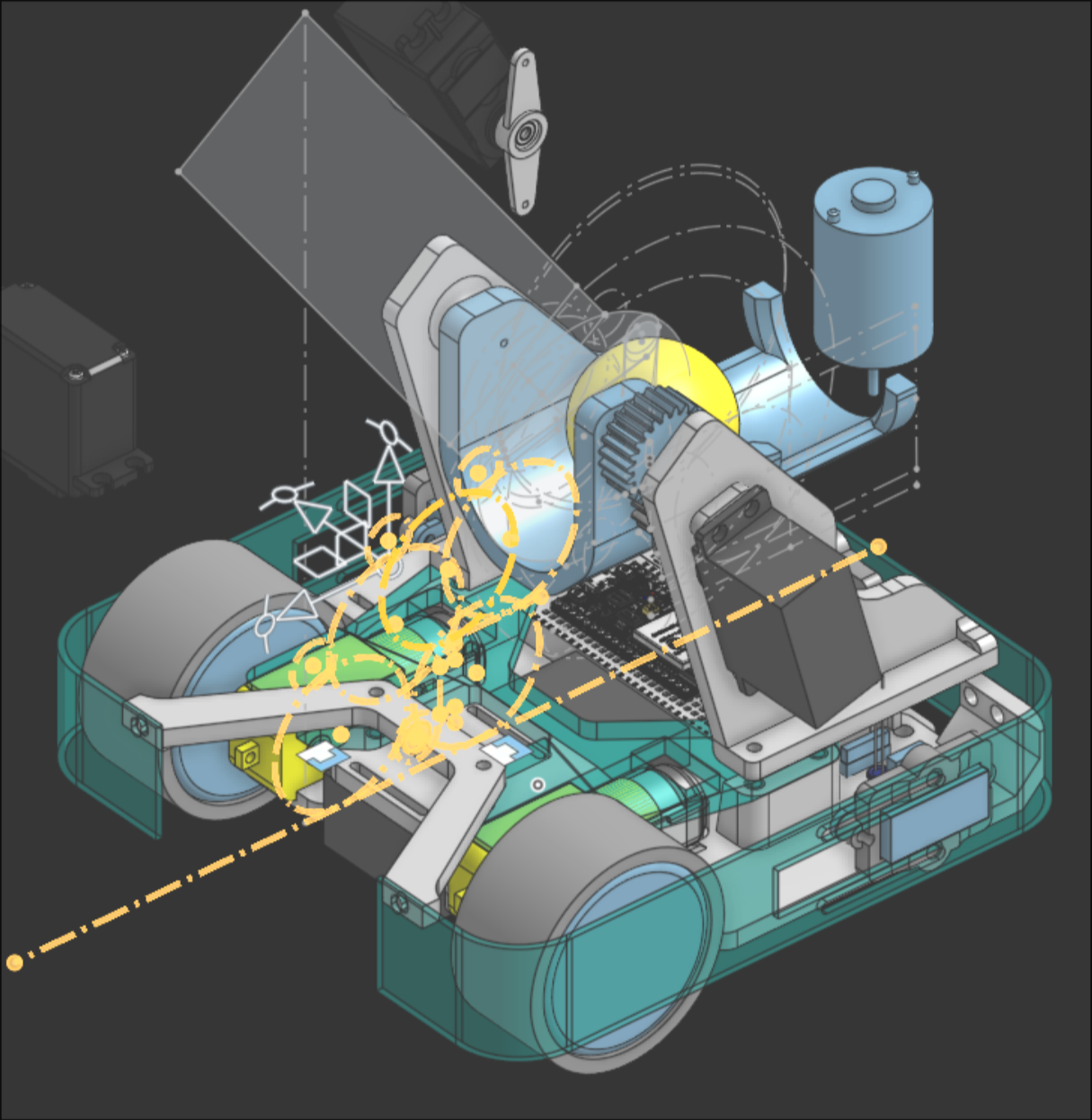
THE REST OF IT:
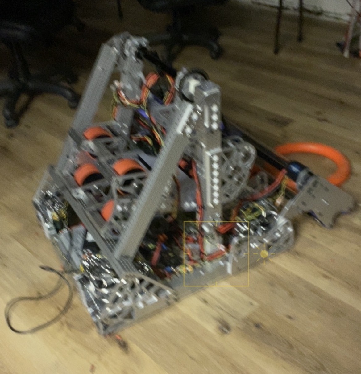
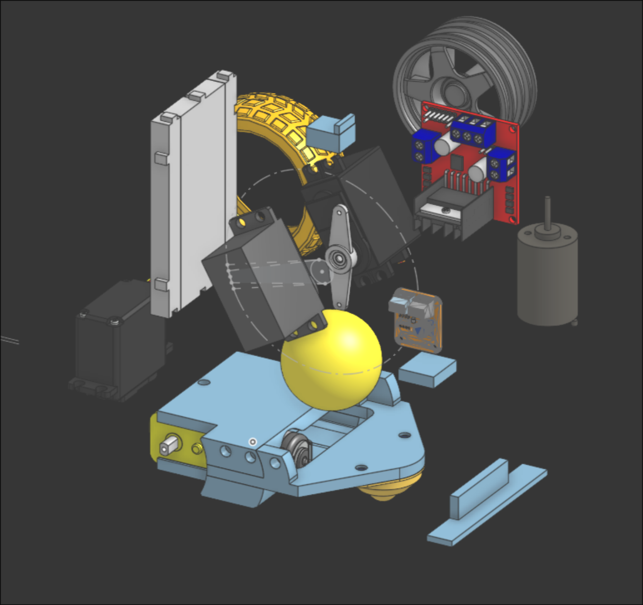
The rest of the robot (the static parts) took much longer. The smaller I made the footprint of the robot, the easier it would make the maze routing. So I tried my best to package all our components in the tightest configuration possible.
Before I began the actual packaging, I measured and modeled all of our parts into the CAD document so I could reference them during design. Some of my team members were interested in learning CAD, so I assigned them some of the designs and also sent them the video I used to teach myself and others who are curious.
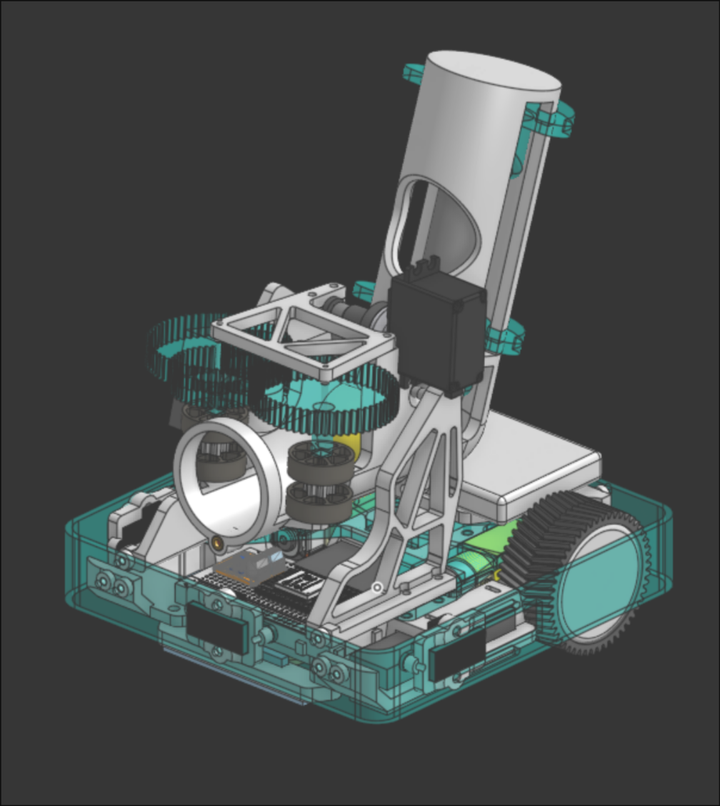
I tried to add more weight around the wheels so it’s easier to control. The color sensor is low and to the front as the software team specified and I was working on adjustable/sliding distance sensors on all sides of the robots. This helped the software team quickly test their maze algorithm with different configurations without having to wait for me to make a redesign.
After learning about our maze pathfinding strategy, I designed this outer rim to assist the robot in the maze. This would allow for more error in the autonomous routine because the rounded and flexible exterior helped the robot slide against the wall if it got stuck.
At first, we thought we would have to pick up balls off the floor. So our robot initially included a ground intake that fed into the shooter.
The (lack of) grip in the wheels were causing issues in the robot’s ability to turn consistently. We didn’t have odometry so when we wanted to rotate autonomously we would just hard code a certain amount of time the robot should turn for. I created grippier, TPU wheels to help aid in the consistency of our turns.

When running tests on competition day, we experienced problems in the launcher gear’s axles popping out of the print. I quickly botched together a solution that would force the top and bottom plates together and prevent the axle from coming out.
The tournament (and participating in the all-nighter before the tournament) was a great time. I didn’t take many photos and I can’t find them online so all I have to show for it is this blurry screenshot.